- Engineering
- Measuring systems
- Machine qualification
-
Components
-
Systems
-
Learn more
-
- Expertise
- About IBS

Learn answers to frequently asked questions about our capacitive measurement systems. Discover unique features and customer benefits and understand how these systems can help you achieve unmatched precision in distance, position and motion measurement.
Capacitive sensors work by measuring changes in the capacitance between two conducting objects with a space between them. In typical capacitive sensing applications, the probe or sensor is one of the conductive objects; the target object is the other. An alternating voltage is applied to the sensor and the current flowing to the object allows the capacitance to be measured. The capacitance is directly proportional to the surface area of the objects and the dielectric constant of the material between them, and inversely proportional to the distance between them. The sizes of the sensor and the target are assumed to be constant as is the material between them. Therefore, any change in capacitance is a result of a change in the distance between the probe and the target. This can be measured at speeds up to 50kHz. Thus the capacitive sensor allows high resolution, high speed, non-contact distance measurement.
Capacitive sensors can provide extremely high precision for distance-related measurement and are ideal for clean environments. The major high and ultra-high precision applications here include sensors used to measure:
For further example applications see our Capacitive Sensors Applications.
Please note that touch sensors which use capacitive sensing represent a different application field with alternative requirements.
The electronics in a sensor are calibrated to generate specific voltage changes for corresponding changes in capacitance. These voltages are scaled to represent specific changes in distance. The amount of voltage changes for a given amount of distance change is called the sensitivity. A common sensitivity setting is 1.0V/10μm. That means that for every 10μm change in distance, the output voltage changes exactly 1.0V. With this calibration, a +2V change in the output means that the target has moved 20μm closer to the probe. Extremely small changes in voltage can be detected in the sensors, such that measurement resolutions as small as 50 picometres can be achieved. For further details on resolution see “What resolutions can I expect for a capacitive sensor?”.
Sensors are factory calibrated for the chosen range and a traceable calibration certificate provided. The calibration system delivers positional accuracies of less than 0.012μm uncertainty and is certified on a regular basis with a NIST traceable laser interferometer. Calibration certificates conform to section 4.8 of ISO 10012-1.
Resolution is defined as the smallest reliable measurement that a system can make. The resolution of a measurement system must be better than the final accuracy the measurement requires. If you need to know a measurement within 0.02μm, then the resolution of the measurement system must be better than 0.02μm. The primary determining factor of resolution is electrical noise. The amount of noise in the output is directly related to bandwidth. When examining resolution specifications, it is therefore critical to know at what bandwidth the specifications apply.
For all sensors, we provide resolution figures at a range of bandwidths. Resolutions as low as 50 picometers at 1kHz Bandwidth can be achieved (See the specifications of our CPL490).
Bandwidths can vary from 100Hz up to 50kHz. Thus as well as static measurements, capacitive sensors can be applied for high speed dynamic measurements, including rotating targets. Switching sensors on and off can be achieved within milli seconds. This can be important for applications where the sensor must not operate during sensitive processes, such as e-beam operation.
The range in which a sensor is useful is a function of the size of the sensing area. The greater the area, the larger the range. The driver electronics are designed for a certain amount of capacitance at the sensor. Therefore, a smaller sensor must be considerably closer to the target to achieve the desired amount of capacitance. In general, the maximum gap at which a sensor is useful is approximately 40% of the sensing area diameter. Sensors are factory calibrated and standard calibrations usually keep the gap considerably less than that.
We offer capacitive sensors for precision applications, with ranges that vary between 10μm and 12.5mm. While all our capacitive sensors have exceptional accuracy, as a rule of thumb; the smaller the range, the higher the accuracy.
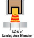
The target size is a primary consideration when selecting a probe for a specific application. The minimum target diameter for standard calibration is 130% of the diameter of the sensing area. The further the probe is from the target, the larger the minimum target size.

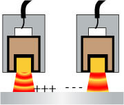
Yes you can. Frequently, a target is measured simultaneously by multiple probes. Because the system measures a changing electric field, the excitation voltage for each probe must be synchronized or the probes would interfere with each other. If they were not synchronized, one probe would be trying to increase the electric field while another was trying to decrease it thereby giving a false reading. Driver electronics can be configured as masters or slaves. The master sets the synchronization for the slaves in multiple channel systems.

Yes they can. Vacuum compatible probes vary from standard probes. They are constructed of 303 stainless steel and the epoxy in the probes has been specifically tested for vacuum applications requiring low outgassing. Probe cabling uses a PTFE jacket which is highly stable and produces very little outgassing. Conductors within the cable and probe are silver-plated, oxygen-free copper (OFC). Vacuum compatibility must therefore be specified if required by the application.
Capacitive sensors are most often used to measure the change in position of a conductive target. But capacitive sensors can be effective in measuring presence, density, thickness, and location of non-conductors as well. Non-conductive materials like plastic have a different dielectric constant than air. The dielectric constant determines how a non-conductive material affects capacitance between two conductors. When a non-conductor is inserted between the probe and a stationary reference target, the sensing field passes through the material to the grounded target. The presence of the non-conductive material changes the dielectric and therefore changes the capacitance. The capacitance will change in relationship to the thickness or density of the material. For example this is applied in the nuclear industry to measure the thickness of oxide layers on nuclear rods.

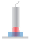
Non-conductors can me measured by passing the electric field through them to a stationary conductive target behind.
The variation in output voltage with distance in a capacitive sensor is not typically linear. The linearity specification is the measurement of how far the output varies from a straight line.
To calculate the linearity error, calibration data is compared to the straight line that would best fit the points. This straight reference line is calculated from the calibration data using a least squares fit. The amount of error at the point on the calibration curve that is furthest away from this ideal line is the linearity error. Linearity error is usually expressed as a percentage of full scale. If the error at the worst point was 0.1 μm and the full-scale range of the calibration was 100 μm, the linearity error would be 0.1%.
Yes. They require the typical considerations of a precision environment. In comparison to inductive sensors, which also use electric fields to measure distance, capacitive sensors typically offer more accuracy. However, unlike inductive they are best used in clean environments as the material in the gap between the sensor and the target, such as oil or moisture due to humidity, will change the dielectric and thus the capacitance based measurement.
Our capacitive sensor systems are compensated to minimize drift due to temperature and have a standard operating range of +4 to +50oC. In this temperature range, errors are less than 0.5% of full scale. A more troublesome problem is that virtually all materials used in targets and fixtures exhibit a significant expansion and contraction over this temperature range. When this happens, the temperature related changes in the measurement are not sensor errors. They are real changes in the gap between the target and the probe. Careful fixture design goes a long way toward minimizing this error and maximizing accuracy. On request, sensors can be made for operation up to 150oC or at cryogenic temperatures.